Switches Ethernet Industriales No Administrados
Switches de carril DIN compactos
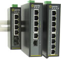
Los Switches no administrados de nivel industrial son dispositivos «plug & play» diseñados específicamente para conectar equipos en entornos de red que están sujetos a temperaturas de funcionamiento extremas de entre -40°C y 75°C, vibraciones e impactos. Han sido fabricados para superar las especificaciones de los Switches comerciales con certificación de seguridad industrial y aprobación para ubicaciones peligrosas, por lo que son idóneos para su uso en condiciones ambientales adversas.
- la automatización industrial y fabril
- la intemperie
- los sistemas de transporte inteligente y por ferrocarril (ITS)
- uso marítimo
- el petróleo y el gas
- la minería
Resistentes y sin necesidad de configuración, Perle cuenta con más de 400 modelos de Switches Ethernet industriales no administrados con un amplio abanico de opciones entre las que figuran 10/100/1000 Ethernet, PoE y fibra. Además de contar con una carcasa de aluminio IP30 resistente a la corrosión, cumplen con diversos estándares reconocidos por la industria para garantizar el máximo nivel de durabilidad y adaptabilidad en condiciones ambientales rigurosas. Las fuentes de alimentación redundantes duales tienen polaridad inversa y protección contra sobrecargas.
Switches no administrados IDS de Perle
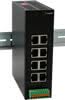
IDS-108GE
Switches Gigabit 8 Puertos
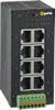
- 8 puertos 10/100/1000Mbps RJ45 Ethernet
- Priorización de QoS (Calidad de servicio)
- Resistencia a vibraciones y golpes
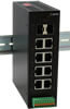
IDS-106GE
Switches Gigabit 8 Puertos
- 6 puertos 10/100/1000Mbps RJ45 Ethernet
- 2 ranuras SFP que admiten 100/1000 Mbps
- Priorización de QoS (Calidad de servicio)
- Resistencia a vibraciones y golpes
IDS-108FE
Switches Ethernet 8 Puertos
- 8 puertos 10/100 Mbps RJ45 Ethernet
- Priorización de QoS (Calidad de servicio)
- Resistencia a vibraciones y golpes
IDS-106FE
Switches ethernet 8 Puertos
- 6 puertos 10/100 Mbps RJ45 Ethernet
- 2 ranuras SFP que admiten 100 Mbps
- Priorización de QoS (Calidad de servicio)
- Resistencia a vibraciones y golpes
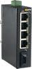
IDS-105FE
Switches Ethernet 5 Puertos
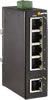
- Priorización de QoS (Calidad de servicio)
- Resistencia a vibraciones y golpes
IDS-104FE
Switches Ethernet 5 Puertos
- 4 puertos 10/100 Mbps RJ45 Ethernet
- 1 puerto SC o ST para 100Base-FX
- Priorización de QoS (Calidad de servicio)
- Resistencia a vibraciones y golpes
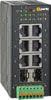
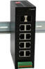
IDS-108HP PoE (90W) Switches
8-port Gigabit Switches
- 8 puertos Ethernet 10/100/1000 RJ45
- 8 puertos PoE suministran hasta 90 vatios de potencia PSE
- Detecte y reinicie a distancia los equipos que no respondan
- Mensajes con prioridad QoS (calidad de servicio)
- Resistencia a vibraciones y golpes
IDS-110HP PoE (90W) Switches
10-port Gigabit Switches
- 2 ranuras SFP compatibles con fibra de 100/1000 Mbps
- 8 puertos Ethernet 10/100/1000 RJ45
- 8 puertos PoE suministran hasta 90 vatios de potencia PSE
- Detecte y reinicie a distancia los equipos que no respondan
- Mensajes con prioridad QoS (calidad de servicio)
- Resistencia a vibraciones y golpes
IDS-114HP PoE (90W) Switches
10-port Gigabit Switches
- 2 ranuras SFP compatibles con fibra de 100/1000 Mbps
- 4 puertos Ethernet 10/100/1000 RJ45
- 4 puertos PoE 10/100/1000 suministran hasta 90 vatios de potencia PSE
- Detecte y reinicie a distancia los equipos que no respondan
- Mensajes con prioridad QoS (calidad de servicio)
- Resistencia a vibraciones y golpes
IDS-108FPP PoE Switch
Switches 8 Puertos

- 8 puertos 10/100Mbps RJ45 Ethernet
- 4 puertos PoE suministran alimentación PSE hasta 30 W
- Certificación para ubicaciones peligrosas
IDS-105GPP PoE Switch
Switches Gigabit 6 o 7 Puertos

- 5 Puertos 10/100/1000Mbps Ethernet RJ45
- 1 o 2 puertos Gigabit Fibra SC o ST
- 4 puertos PoE suministran alimentación PSE hasta 30 W
- Certificación para ubicaciones peligrosas
¿Por qué elegir un Switch industrial IDS de Perle?
Perle, expertos en el entorno industrial
Llevamos más de 40 años diseñando hardware industrial para Modbus y PROFINET para entornos de conversión de Ethernet. Esta experiencia se ha usado para diseñar los Switches Ethernet más resistentes del mercado. Los Switches IDS-300 e IDS-500 de Perle, con el conjunto de funciones PRO, se pueden gestionar a través de sistemas PLC, NMS, HMI o SCADA que usan PROFINET o Modbus TCP. Además, MRP (IEC 62439-2) ofrece una convergencia rápida en una topología de red industrial de anillos.
Temperatura industrial
Muchos fabricantes aseguran un funcionamiento de entre -40ºC y 75ºC, pero utilizan componentes comerciales que fallarán en entornos con temperaturas extremadamente altas o bajas. Los circuitos integrados del PCB se sobrecalentarán y los conectores de gama baja no permitirán un contacto adecuado entre el dispositivo y los cables. Para evitar estas situaciones, todos los componentes utilizados en los Switches de temperatura industrial de Perle han sido diseñados y probados para soportar temperaturas de funcionamiento entre -40ºC y 75ºC.
Cumplimiento de los estándares
Para garantizar que el sistema funcione con dispositivos compatibles con Ethernet y aplicaciones IP, los Switches IDS de Perle usan los protocolos basados en los estándares IEEE. De este modo, se facilita la integración entre los equipos industriales y las aplicaciones de oficinas comerciales. Estos estándares reconocidos por la industria garantizan el máximo nivel de duración y adaptación en condiciones ambientales adversas.
Sólidos y fiables
Perle únicamente utiliza componentes de alta tecnología de los principales fabricantes de chips occidentales para garantizar la fiabilidad de los productos. Esto nos permite publicar con orgullo los indices de MTBF elevados en las especificaciones de hardware de cada producto. Y respaldamos esta fiabilidad con la mejor garantía de su clase.
Asistencia técnica
Nuestro personal de asistencia técnica y ventas está presente por todo el mundo para ayudarle. Si necesita ayuda para elegir el mejor Switch de Carril DIN para su aplicación, le ofrecemos asistencia técnica por teléfono o correo electrónico. Y, a pesar de que los Switches Industriales Perle son muy fáciles de instalar y configurar, puede ponerse en contacto con el soporte postventa e forma sencilla.
Confianza
Perle presta soluciones de confianza para la conectividad de dispositivos desde 1976. Más de 40 años de experiencia en los que empresas de todo el mundo han depositado su confianza en nosotros para que prestemos una tecnología de conectividad superior para las aplicaciones clave de sus proyectos. Si el tiempo de actividad de su red es un elemento crucial para su éxito, escoja productos de calidad. Escoja Perle.
La calidad del Switch Ethernet que elija afectará el tiempo de actividad de su red. Elige productos de calidad. Elige a Perle.