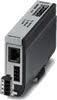
DT-TELE-SHDSL Protector de sobretensión
Protector de sobretensión DSL Modem
- Protección para interfaces de telecomunicaciones SHDSL
- Adaptador de protección para dos pares de señales mediante conector RJ45 (RJ12) o conector atornillado
- Carcasa metálica resistente
- Dos puertos SHDSL
El protector de sobretensión DT-TELE-SHDSL ha sido diseñado para cumplir los requisitos especiales de transmisión de datos SHDSL. Ha sido especialmente diseñado para proporcionar protección contra rayos, interferencias de radiofrecuencia, descargas electrostáticas y sobretensiones transitorias para la máxima seguridad de los datos con una mínima atenuación de la señal.
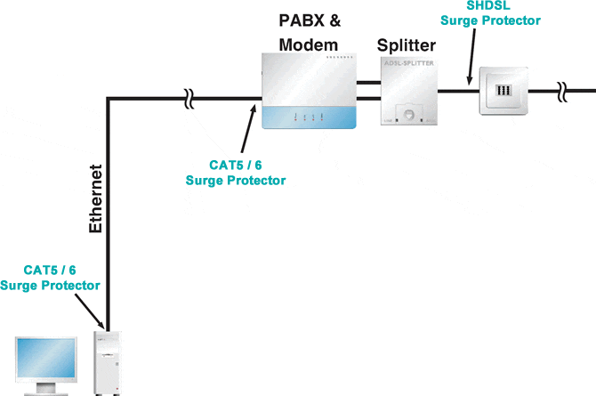
Protección contra sobretensiones para sistemas SHDSL
Las telecomunicaciones fiables son imprescindibles en la industria de hoy. Los sistemas sensibles utilizados en estos casos funcionan con altas frecuencias en niveles de baja señal y están conectados en red sobre un área amplia. Las subidas de tensión conducen rápidamente a errores importantes y, en el peor de los casos, la pérdida de datos. El protector de sobretensión SHDSL adopta la forma de un adaptador que se puede instalar fácilmente entre cables de telecomunicaciones de entrada y un módem. La conexión por enchufe garantiza una instalación rápida y flexible y sólo necesita estar conectado a tierra mediante el cable negro o base de carril DIN.
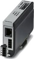
Conector macho con protección contra sobretensiones para dos interfaces de telecomunicaciones SHDSL (puertos). Conexión: RJ45 (RJ11/RJ12) y bloque de terminales de tornillo conectables (COMBICON). Como alternativa, se puede fijar a un carril DIN.

Specifications
HTSUS Number:
8535.40.0000
UNSPSC Code:
39121621
ECCN:
5A991


Ambient Conditions
Ambient temperature (operation)
-40°C ... 85°C
Ambient temperature (storage/transport)
-40°C ... 85°C
Degree of protection
IP20
Protective circuit
IEC test classification
- B2
- C1
- C2
- C3
- D1
Maximum continuous voltage UC
185 V DC
Rated current
≤ 380 mA (25°C)
Operating effective current IC at UC
≤ 6 µA
Residual current IPE
≤ 4 µA
Nominal discharge current In (8/20) µs (Core-Core)
≤ 5 kA
Nominal discharge current In (8/20) µs (core-earth)
≤ 5 kA
Total discharge current Itotal (8/20) µs
10 kA
Nominal pulse current Ian (10/700) µs (Core-Core)
150 A
Nominal pulse current Ian (10/700) µs (Core-Earth)
150 A
Voltage protection level Up (core-core)
- 250 V (B2 - 100 A)
- ≤ 250 V (C1 - 500 A)
- ≤ 410 V (C2 - 5 kA)
Voltage protection level Up (core-ground)
- ≤ 580 V (B2 - 100 A)
- ≤ 580 V (C1 - 500 A)
Response time tA (core-core)
≤ 100 ns
Response time tA (core-earth)
≤ 100 ns
Input attenuation aE, sym.
- typ. 0.3 dB (≤ 2,8 MHz / 100 Ω)
- typ. 3 dB (≤ 25 MHz / 100 Ω)
Cut-off frequency fg (3 dB), sym. in 100 Ohm system
25 MHz
Capacity (core-core)
55 pF
Capacity (core-earth)
7 pF
Surge protection fault message
None
Impulse durability (conductor-conductor)
C1 - 1 kV/500 A
Impulse durability (conductor-ground)
- B2 - 4 kV/100 A
- C1 - 1 kV/500 A
- C2 - 10 kV/5 kA
VDE requirement class
- B2
- C1
- C2
- C3
- D1
Maximum continuous voltage UC
130 V AC
Pulse discharge current Iimp (10/350) µs
2.5 kA (Number of pulses category D1)
Nominal pulse current Ian (10/1000) µs (Core-Core)
100 A
Nominal pulse current Ian (10/1000) µs (Core-Earth)
100 A
Voltage protection level Up (core-core)
≤ 250 V (C3 - 100 A)
Voltage protection level Up (core-ground)
- ≤ 790 V (C2 - 5 kA)
- ≤ 300 V (C3 - 100 A)
Resistance in series
3.3 Ω 20 %
Impulse durability (conductor-conductor)
- C2 - 10 kV/5 kA
- B2 - 4 kV/100 A
Impulse durability (conductor-ground)
D1 - 1 kA
Standards and Regulations
Standards / specifications
- IEC 61643-21 2002
- IEC 61643-21
General
Housing material
Zinc die-cast
Color
silver/black
Mounting type
Connection-specific attachment plug and DIN rail, 35 mm
Design
Attachment plug for DIN rail mounting
Number of positions
4
Direction of action
Line-Line & Line-Ground/Shield
Standards for cearances and creepage distances
- IEC 60664-1
- VDE 0110-1
Connection, equipotential bonding
Connection method
Cable connection/DIN rail
Connection data
Connection method
RJ45/COMBICON
Connection method IN
RJ45 socket
Connection method OUT
RJ45 socket
Connection method IN
MC 1,5/4
Connection method OUT
MC 1,5/4
Connection technology
Screw connection
Screw thread
M2
Tightening torque
0.22 Nm
Stripping length
7 mm
Conductor cross section flexible
0.14 mm² ... 1.5 mm²
Conductor cross section solid
0.14 mm² ... 1.5 mm²
Conductor cross section AWG
28 ... 16
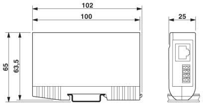
Dimensions
Height
103 mm
Width
25 mm
Depth
63 mm
Approvals
- UL Listed
- EAC
Commercial data
Packing unit
1
Weight per piece
320.0 g
Country of origin
Germany
Application Diagrams
Circuit Diagram
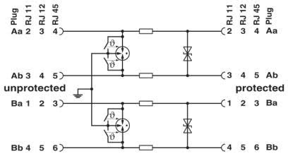
Protection Against Surge Voltage
Número de producto: 28015938
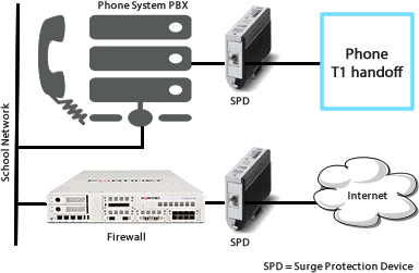
DT-TELE-SHDSL Surge Protector - surge protection device for two SHDSL telecommunications interfaces (ports). Connection: RJ45 (RJ12/RJ11) and plug-in screw terminal block
Power Cord: None -- Power Cord not included.